VIBRA-SYNC® Basic Troubleshooting
Confirm the Hub and Node are powered and that the red power LED is illuminated.
Verify the local Wi-Fi network is working by connecting with a phone or computer and accessing any webpage.
Use the VIBRA-SYNC® mobile app to connect the Hub to Wi-Fi. A solid green LED indicates the Hub is successfully connected.
Confirm that your machine and Sensor appear in the VIBRA-SYNC® Web App. Contact ACTION if additional setup assistance is needed at (503) 537-1111.

Understanding the Issue
If VIBRA-SYNC® is not displaying machine data, the issue is typically related to power, network connectivity, communication between system components, or initial setup. The following Hub, Node, and Sensor sections explain what to check for each VIBRA-SYNC® component.
VIBRA-SYNC® Hub
Power & Status
The VIBRA-SYNC® Hub operates on 12 VDC using the supplied power adapter. Use the VIBRA-SYNC® mobile app to connect the Hub to Wi-Fi.
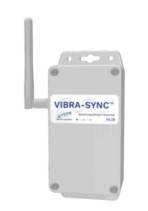 |
During normal operation: 🔴 Red LED — Solid when the Hub is powered on. 🟢 Green LED — Solid when the Hub is connected to Wi-Fi. 🔵 Blue LED — Flashes periodically when one or more Nodes are communicating with the Hub. |
The VIBRA-SYNC® Web App must also be configured before machine data can be logged. If setup issues persist after repeating the setup process, contact ACTION for assistance.
Mesh Network Configuration
The VIBRA-SYNC® Hub and Nodes communicate through a mesh network. Most installations use a single Hub with multiple Nodes operating on the same mesh channel.
The rotary dial switch inside the Hub and each Node must be set to the same channel value. The factory default is 0 (zero), and this setting is appropriate for most installations. Alternate channel settings are only required for specialized applications with multiple mesh networks.
If multiple mesh networks are needed, contact ACTION for assistance at (503) 537-1111.
VIBRA-SYNC® Node
Power & Communication
Each machine uses one VIBRA-SYNC® Node and at least one VIBRA-SYNC® Sensor. The Node accepts 100–480 VAC (50/60 Hz) or 12 VDC power and may be wired to the machine motor or to an always-on power source.
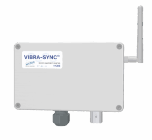 |
During normal operation: 🟢 Green LED — When VIBRA-SYNC® is connected to the Mesh. ⚪ White LED — Flashes when communication is coming into the Sensor. 🔵 Blue LED — Flashes when sending data to the Sensor. |
If communication is lost, verify the Node has power, the Sensor is connected and powered, and the Hub is operating normally.
Mesh Network Configuration
The Node communicates with the Hub through the mesh network. Verify the rotary channel switch matches the Hub setting. The factory default is 0, which is used for most installations.
VIBRA-SYNC® Sensor
Power & Communication
The VIBRA-SYNC® Sensor receives power from the Node through the supplied harness.
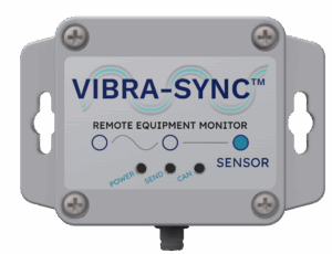 |
During normal operation: 🔴 Red LED — Solid when the Sensor is powered on. ⚪ White LED — Flashes when communication is going out to the Node. 🟢 Green LED — Flashes when Node communication is received. |
If the Sensor is not communicating, verify the Node has power and the wiring harness is securely connected.
Sensor Address Configuration
Each Sensor on a Node’s CAN bus must have a unique address.
The rotary switch inside the Sensor enclosure sets the Sensor number.
-
0 — First Sensor (typically mounted on the pan drive bracket)
-
1 — Second Sensor
-
2–15 — Additional Sensors as required
Each Sensor connected to the same Node must use a unique address. CAN bus addresses are independent for each machine, so every Node may include a Sensor configured as 0 (zero).